Comprehensive Modernization of a 60 MVA 132 kV Power Transformer
Challenge
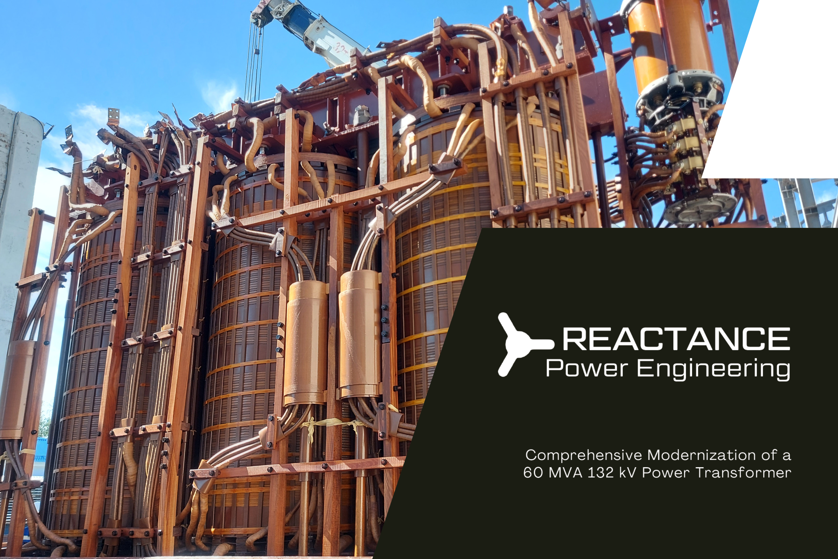
A 60 MVA, 132 kV transformer with nearly 30 years of operation required more than routine maintenance. Ageing effects, thermal cycling, and lack of monitoring created increasing operational risk. The objective was to extend service life and upgrade the unit to modern reliability standards — without full replacement.
What We Did
Full internal inspection and active part assessment
Magnetic system verification and debris elimination
Insulation refurbishment in critical areas
Tank modernization with sensors and monitoring interfaces
Key component replacement and diagnostics integration
Result
Tests: Passed all post-modernization tests.
Reliability: Restored structural and dielectric integrity.
Service Life: Extended by 10+ years.
Monitoring: Real-time condition monitoring enabled.
| Type | Three-phase three winding transformer |
| Rated power, MVA | 60/60/60 |
| Nominal voltage (HV/MV/LV), kV | 132/33/6.6 |
| Vector group | YNYND0-11 |
| Voltage regulation, range, No. of steps | OLTC on HV side, ±9×1,78% |
| Rated frequency, Hz | 50 |
| Cooling system | ONAN/ONAF |
Failure Analysis & OLTC Flashover Investigation – 50 MVA, 220/20 kV Transformer
Challenge
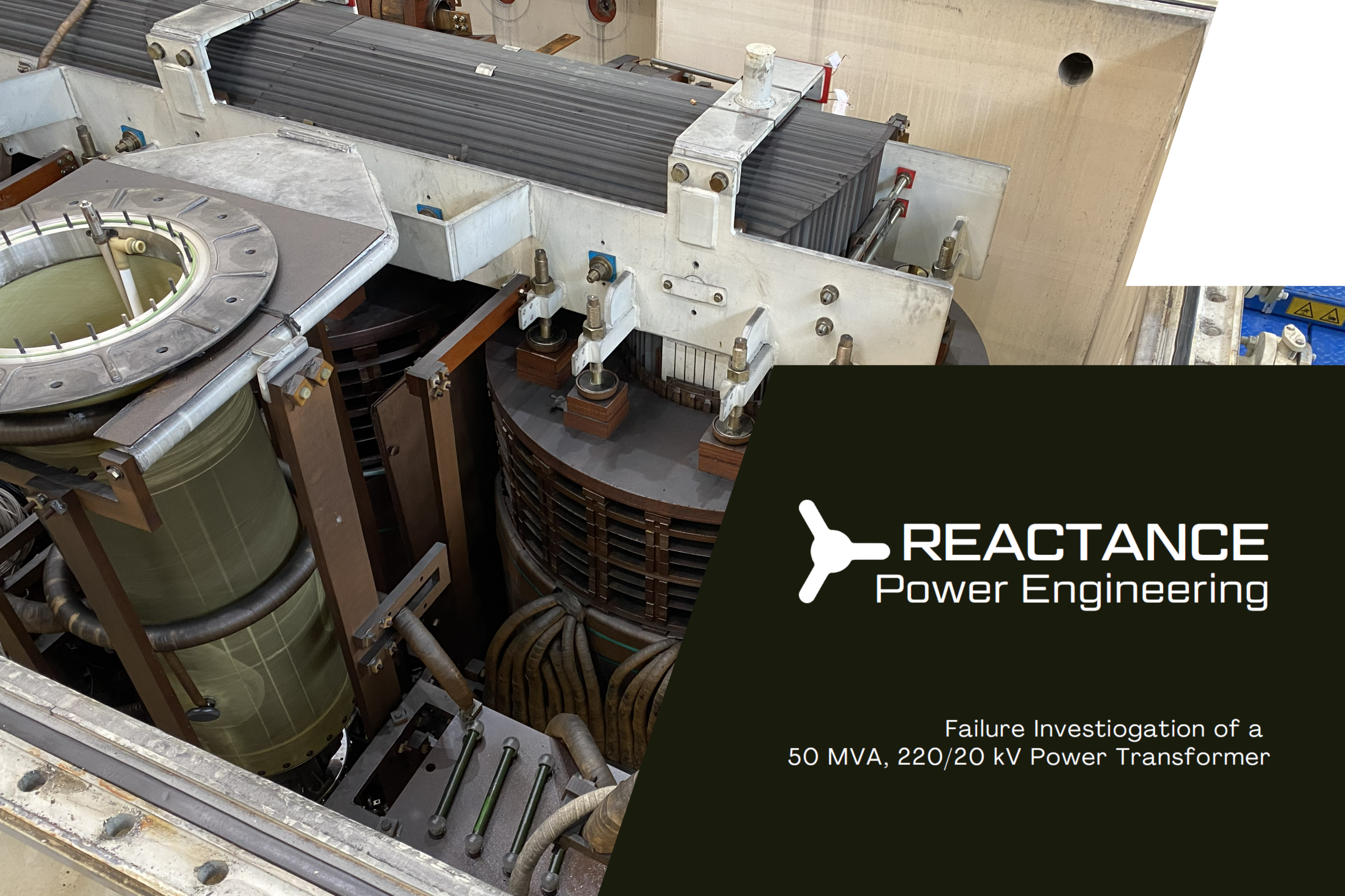
A transformer experienced a severe internal fault with pressure build-up, tank deformation, and oil contamination. Initial diagnostics indicated high-energy discharge and abnormal gas generation. The key challenge was to identify the root cause and assess internal damage to support repair or replacement decisions.
What We Did
Full internal inspection and failure investigation
Identified OLTC selector failure with broken components and flashover
Analyzed arcing traces on tap leads and selector contacts
Assessed structural damage including broken supports and insulation
Evaluated oil condition with high carbon contamination and fault gases
Reviewed SFRA, IR, PI test data to assess winding condition
Result
Root Cause: OLTC internal failure and flashover identified.
Damage Assessment: Clear extent of affected components established.
Recommendations: Actionable repair and risk mitigation guidance provided.
Decision Support: Informed choice between refurbishment and replacement.
| Type | Three-phase two winding transformer |
| Rated power, MVA | 50/50 |
| Nominal voltage (HV/LV), kV | 220/20 |
| Vector group | Dyn1 |
| Voltage regulation, range, No. of steps | OLtc on HV side, ±20x0,5% |
| Rated frequency, Hz | 50 |
| Cooling system | ONAN |
Mitigating Local Partial Discharges in OLTC Console Area – 420 kV Autotransformer
Challenge
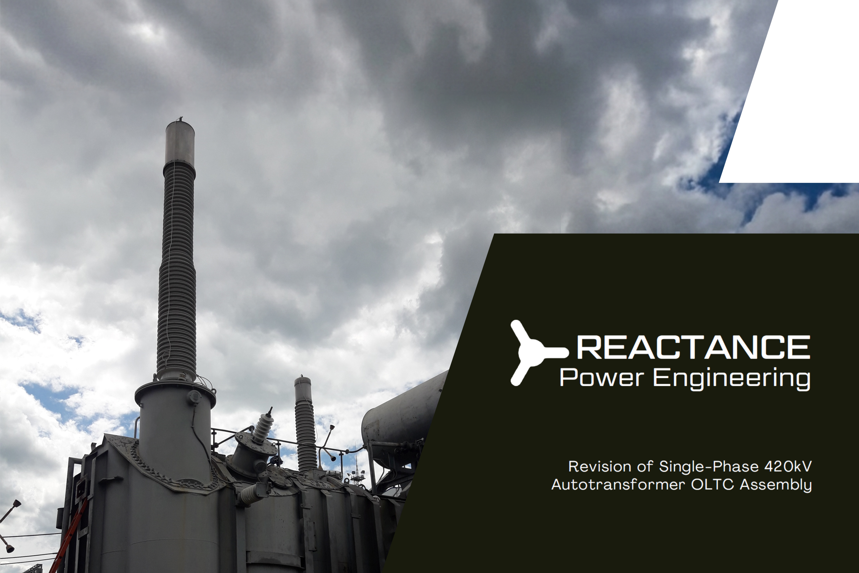
During internal inspection of a 420 kV single-phase autotransformer, signs of oil decomposition and localized overheating were detected in the OLTC mechanical console area. Not linked to load currents, the issue indicated a long-term design-related problem. The objective was to identify the root cause and eliminate thermal stress without major structural modifications.
What We Did
Detailed inspection of OLTC internal structure and affected zones
Identified capacitive coupling between grounded and "floating" parts
Determined risk of circulating currents and partial discharges in console
Developed corrective solution based on equipotential bonding principles
Implemented grounding connection between metallic components
Verified compliance with modern insulation coordination practices
Result
Root Cause: Floating conductive structure causing localized electrical stress.
Correction: Partial Discharges eliminated through simple and robust design fix.
DGA: Stabilization of gas results and oil condition confirmed.
| Type | One-phase autotransformer |
| Rated power, MVA | 167/167/50 |
| Nominal voltage (HV/MV/LV), kV | 500/220/38.5 |
| Vector group | YNyn0 + d11 |
| Voltage regulation, range, No. of steps | OLTC on MV side, ±6×2,1% |
| Rated frequency, Hz | 50 |
| Cooling system | OFAF |
Let's build something great together.
Get in touch →| Type | TBD |
| Rated power, MVA | TBD |
| Rated voltage, kV | TBD |
| Vector group | TBD |
| Voltage regulation, range, No. of steps | TBD |
| Rated frequency, Hz | TBD |
| Cooling system | TBD |
| Special requirements | TBD |
Most Reactance assignments are performed under strict confidentiality. For this reason, client names, OEMs and project locations are not disclosed publicly. The following anonymized references illustrate the type, scale and complexity of our work. More detailed references may be shared under NDA.