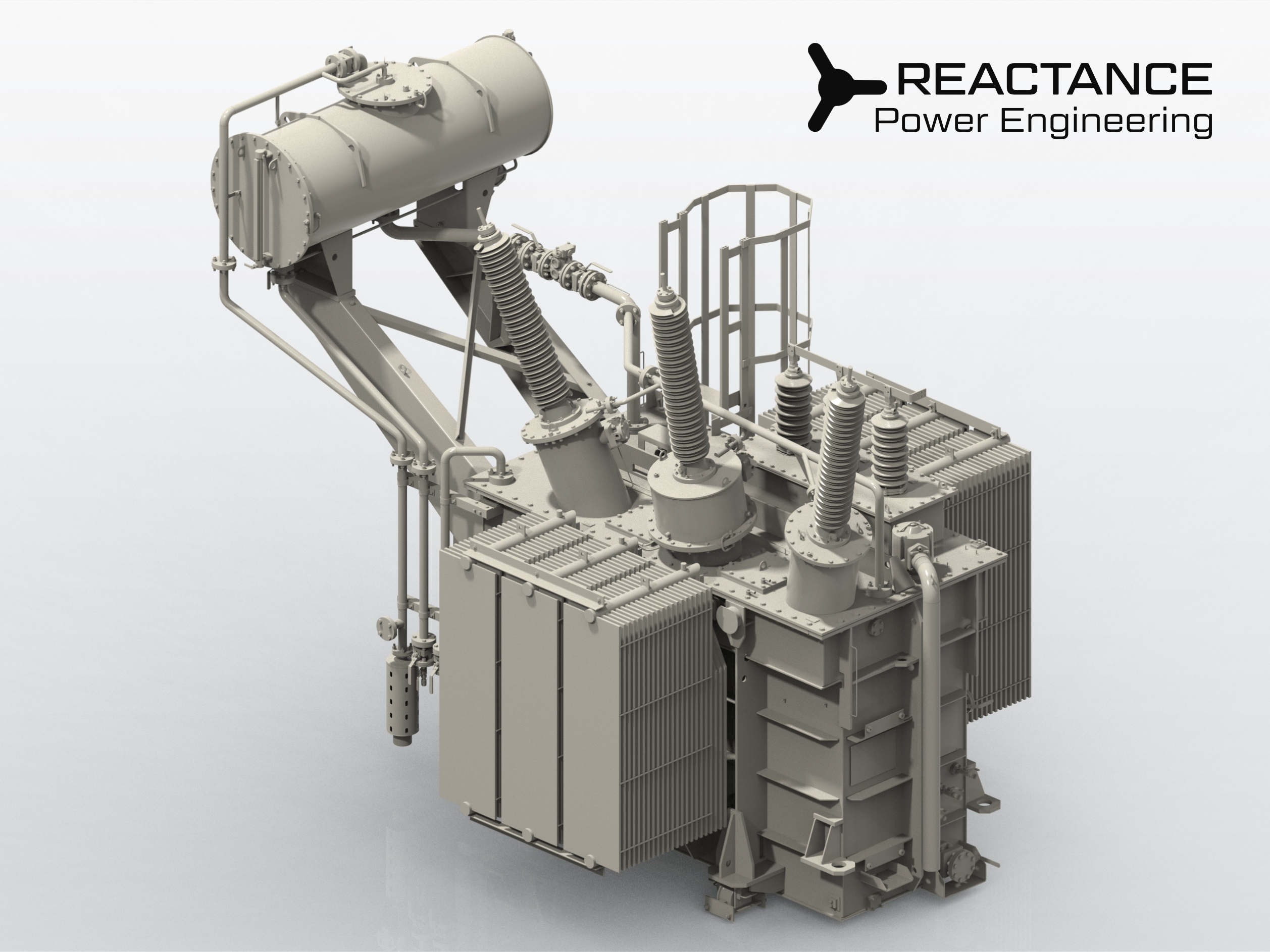
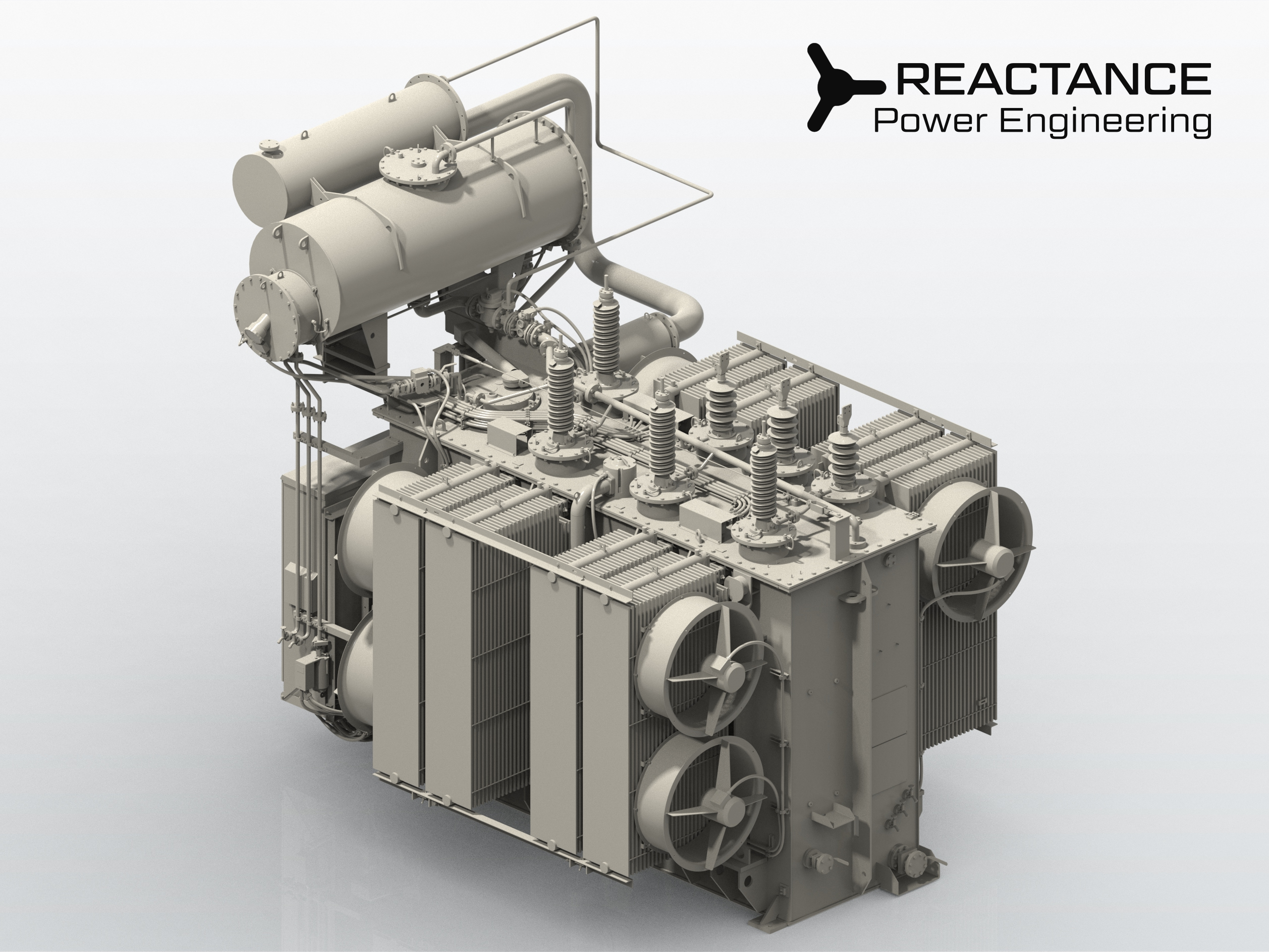
400 kV Transformer Design for Seismic Conditions
Challenge
A complex, high-stakes project for a major National Grid operator. The design required strict adherence to rigorous utility standards working under extreme environmental conditions.
What we did
We delivered a comprehensive turnkey engineering package, from initial pre-bid calculations to the final as-built documentation. Our engineering team performed advanced Structural & Modal Analyses to identify resonance risks during seismic events. Based on simulation results, we optimized critical load-bearing components and high-stress nodes. The process was validated through a formal Design Review by an independent third-party expert.
Result
Zero-Defect Approval: Passed all independent technical audits without a single comment or revision.
Performance Validated: Successfully manufactured, passed all FAT, currently operational at the end-user's site.
| Type | Three-phase three winding transformer |
| Rated power, MVA | 170/170/17 |
| Rated voltage (HV/MV/LV), kV | 400/63/20 |
| Vector group | YNd11d11 |
| Voltage regulation, range, No. of steps | OLTC on HV side, ±10×1,25% |
| Rated frequency, Hz | 50 |
| Cooling system | ONAN/ONAF |
| Special requirements | Heavy seismic PGA 0.3 g |
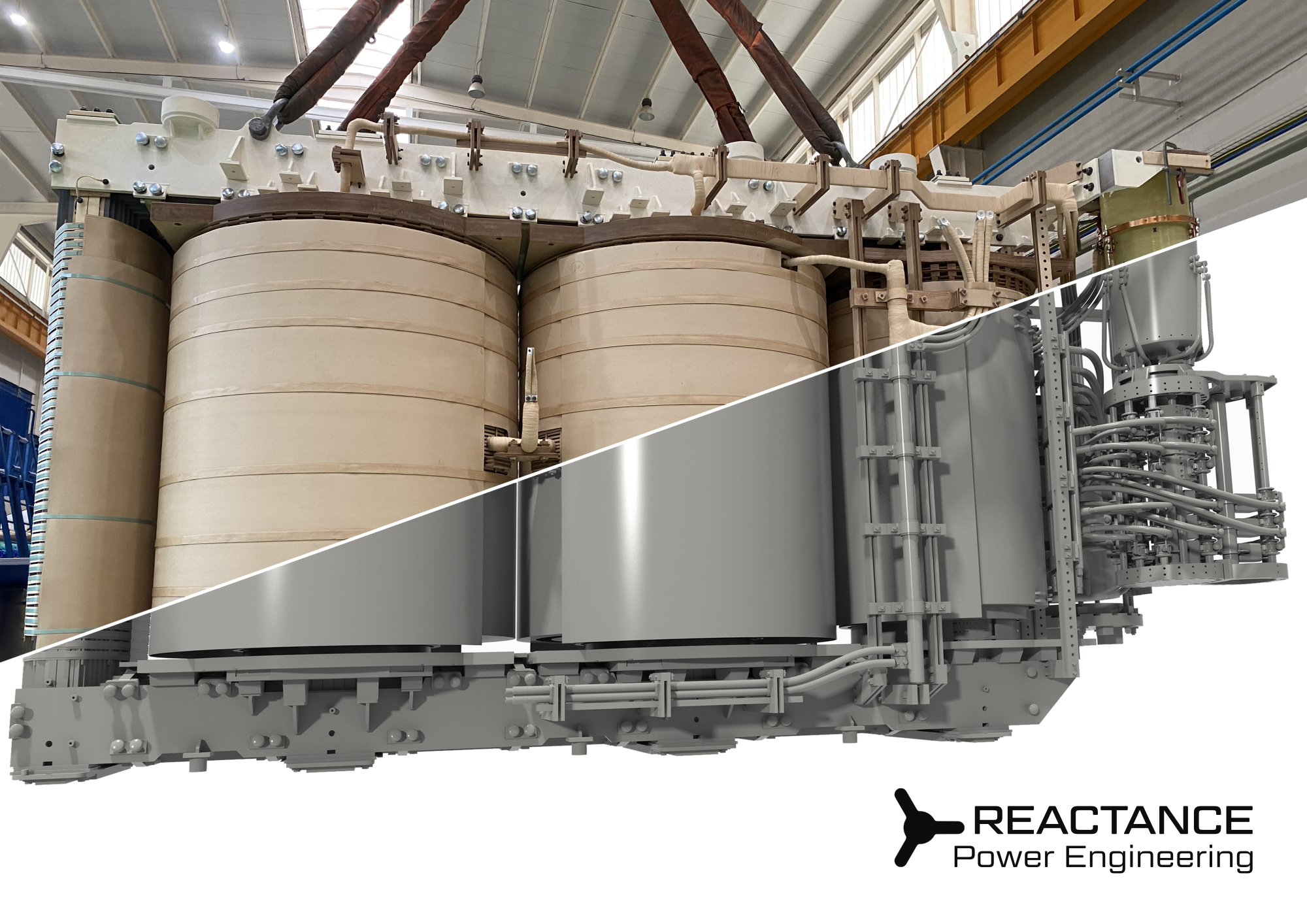
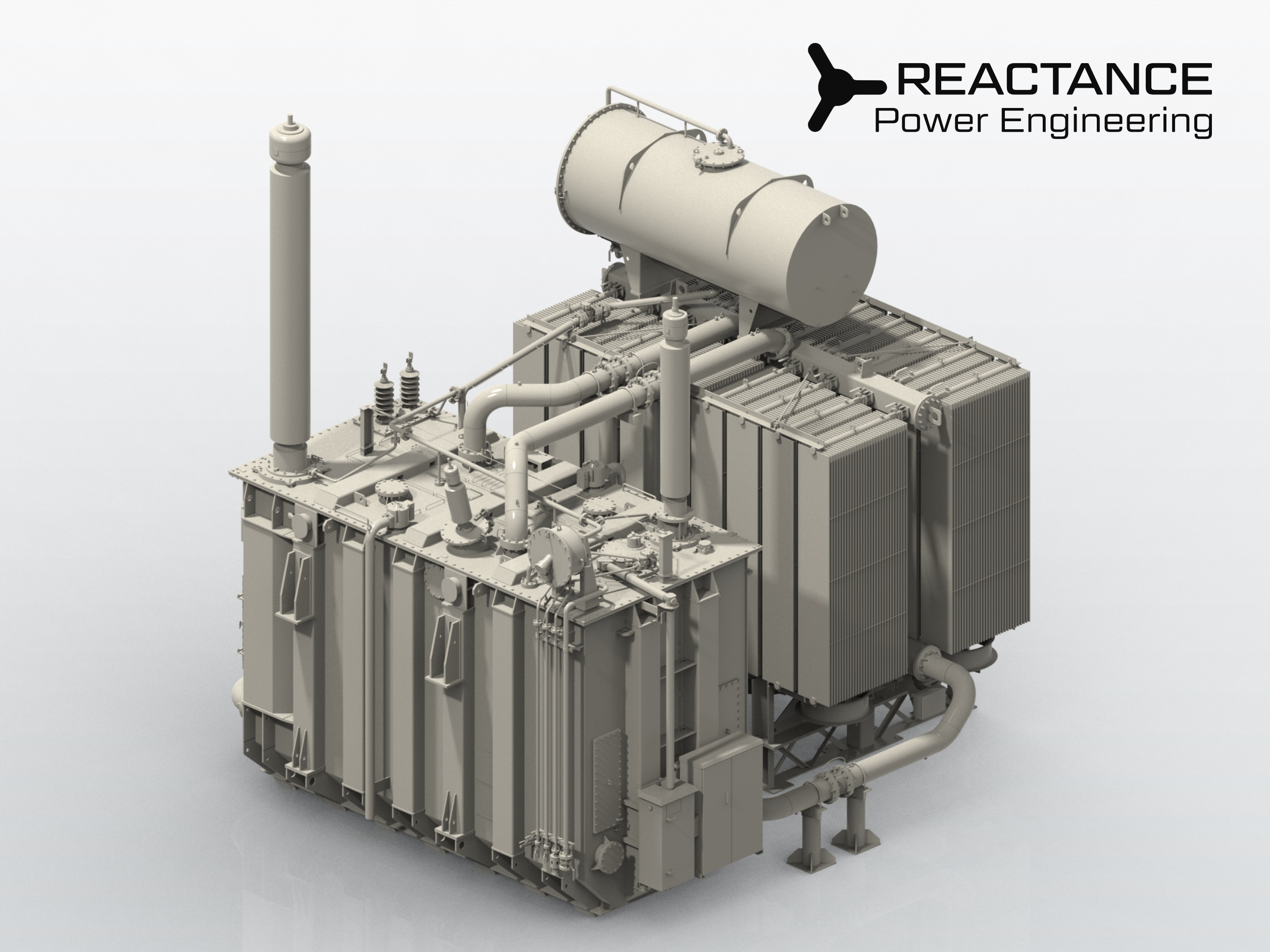
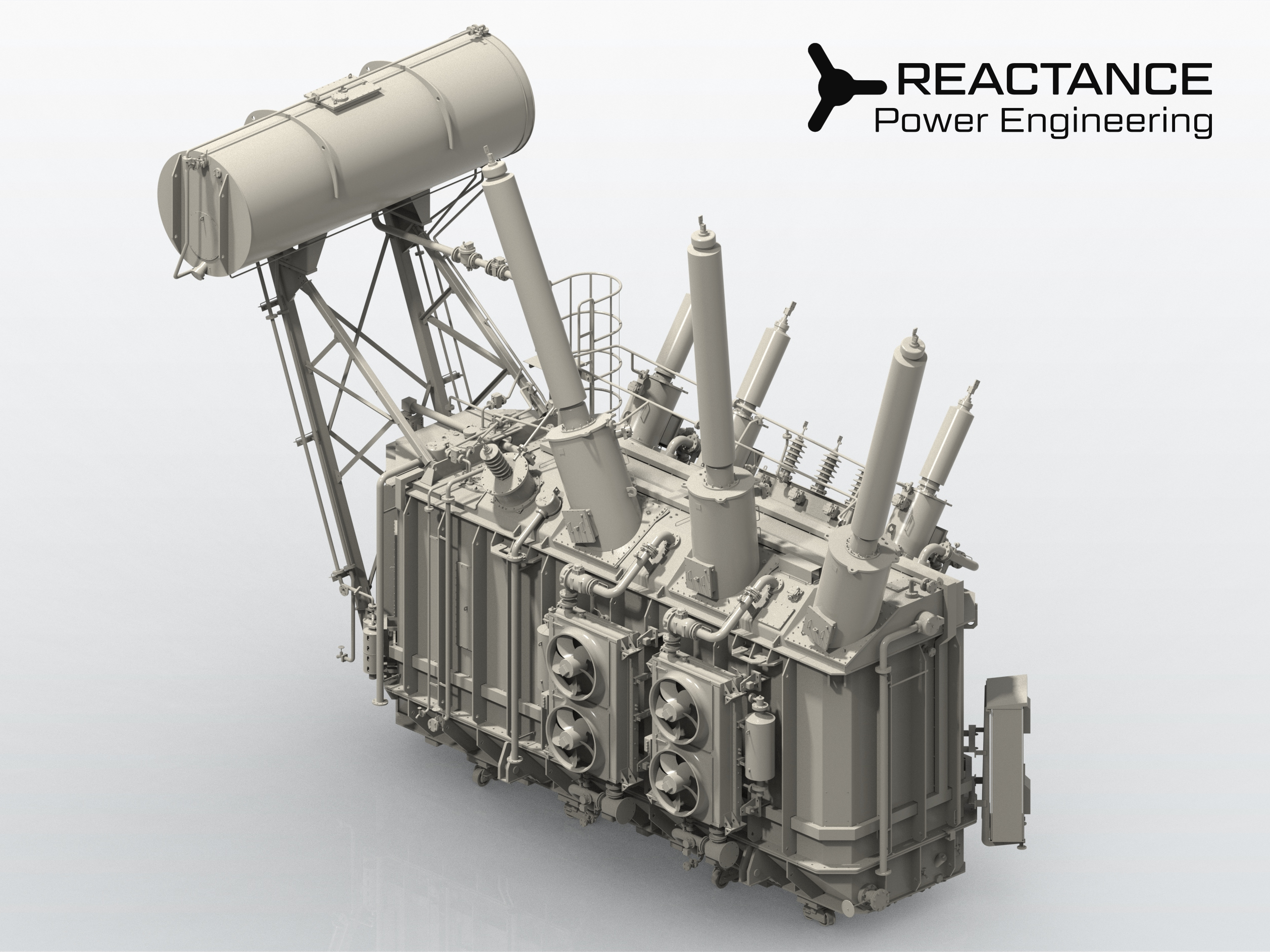
400 kV Transformer Design for Renewable Energy Integration
Challenge
A high-complexity project for a leading European Renewable IPP. The task required managing extreme dielectric stresses and strict transport height limitations.
What we did
We engineered a 5-column core structure (3 main, 2 side limbs) to optimize magnetic flux and meet restrictive shipping clearances. To handle high test voltages, we integrated Zn-O varistors for advanced OLTC protection against transient overvoltages. The design featured three single-phase OLTCs linked by a single mechanical drive to eliminate the risks associated with electronic synchronization.
Result
Technical Excellence: Passed all rigorous high-voltage dielectric tests and FAT with zero deviations.
Operational Reliability: Successfully delivered and commissioned, providing a robust interconnection for large-scale renewable power generation.
| Type | Three-phase autotransformer |
| Rated power, MVA | 320/320/32 |
| Rated voltage (HV/MV/LV), kV | 400/132/30 |
| Vector group | YNa0d11 |
| Voltage regulation, range, No. of steps | OLTC on HV side, ±12×1,25% |
| Rated frequency, Hz | 50 |
| Cooling system | ONAN/ONAF1/ONAF2 |
| Special requirements | Five-limb core |
145 kV Shunt Reactors for Offshore & Coastal Environments
Challenge
A specialized project for a National TSO involving the deployment of shunt reactors at island and coastal substations. The design had to withstand an extreme C5-M marine environment while meeting ultra-low noise emission limits for sensitive locations.
What we did
To ensure maximum durability, we implemented a comprehensive anti-corrosion strategy, including specialized hardware selection and moisture-sealing geometry to eliminate crevices. To achieve ultra-low noise levels, we developed a unique core-clamping architecture and utilized sound-damping steel plates for the tank construction, backed by advanced acoustic simulations.
Result
Environmental Resilience: The units successfully passed all C5-M certification requirements and noise level audits.
Successful Deployment: All reactors are currently operational, providing critical reactive power compensation for island grid stability.
| Type | Three-phase shunt reactor |
| Rated power, MVAr | 9 |
| Rated voltage (HV), kV | 132 |
| Vector group | YN |
| Voltage regulation, range, No. of steps | — |
| Rated frequency, Hz | 50 |
| Cooling system | ONAN |
| Special requirements | Low noise design |
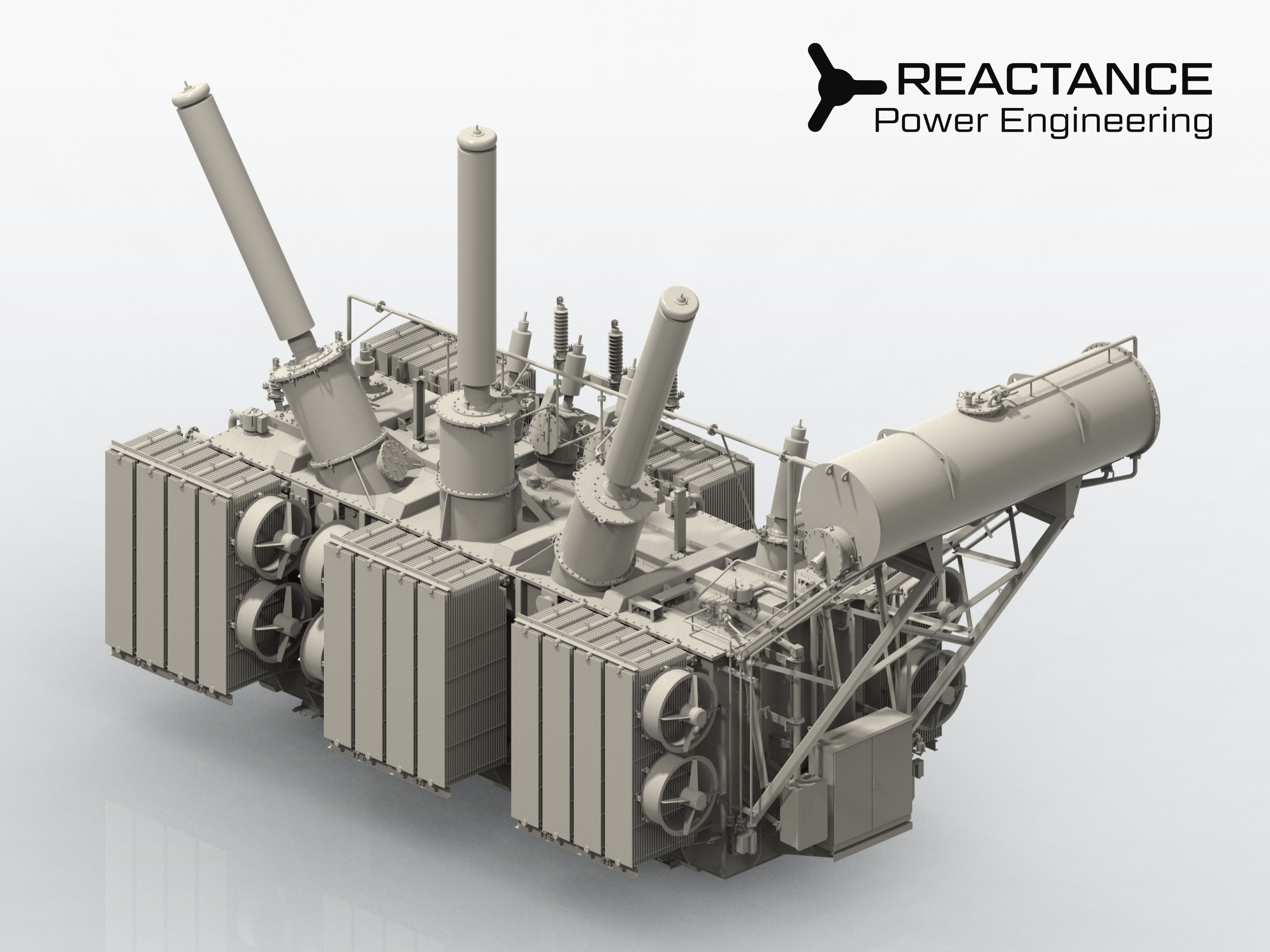
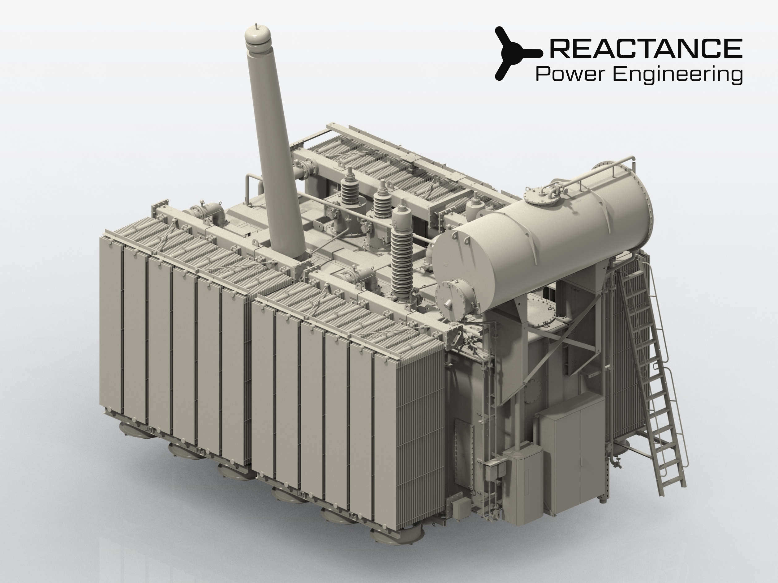
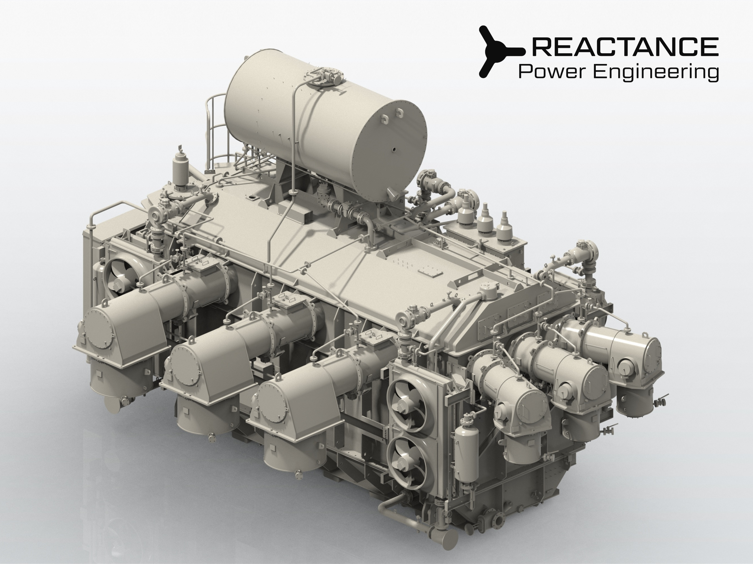
400 kV High-Efficiency Autotransformer Bank
Challenge
A high-performance project for a major solar energy producer. The specification demanded No-Load and Load losses lower than standard IEC 60076 requirements, posing a substantial electromagnetic design challenge within strict weight and size constraints.
What we did
We performed high-precision electromagnetic modeling to achieve an ultra-low loss profile. Following the client's request, we engineered a specialized Separate Radiator Bank on a self-supporting structural frame. This modular cooling system was designed for transport in a fully assembled state, drastically reducing site assembly time and labor costs.
Result
Efficiency Benchmark: Successfully met the ultra-low loss targets, providing the end-user with long-term operational savings.
Fast Installation: The modular cooling system allowed for rapid on-site commissioning, meeting the tight deadlines of the renewable energy project.
| Type | One-phase autotransformer |
| Rated power, MVA | 217/217/0.25 |
| Rated voltage (HV/MV/LV), kV | 400/220/30 |
| Vector group | YNa0d11 (three-phase bank) |
| Voltage regulation, range, No. of steps | OLTC on HV side, ±10×1,5% |
| Rated frequency, Hz | 50 |
| Cooling system | ONAN/ONAF |
| Special requirements | Separated Radiator Bank |
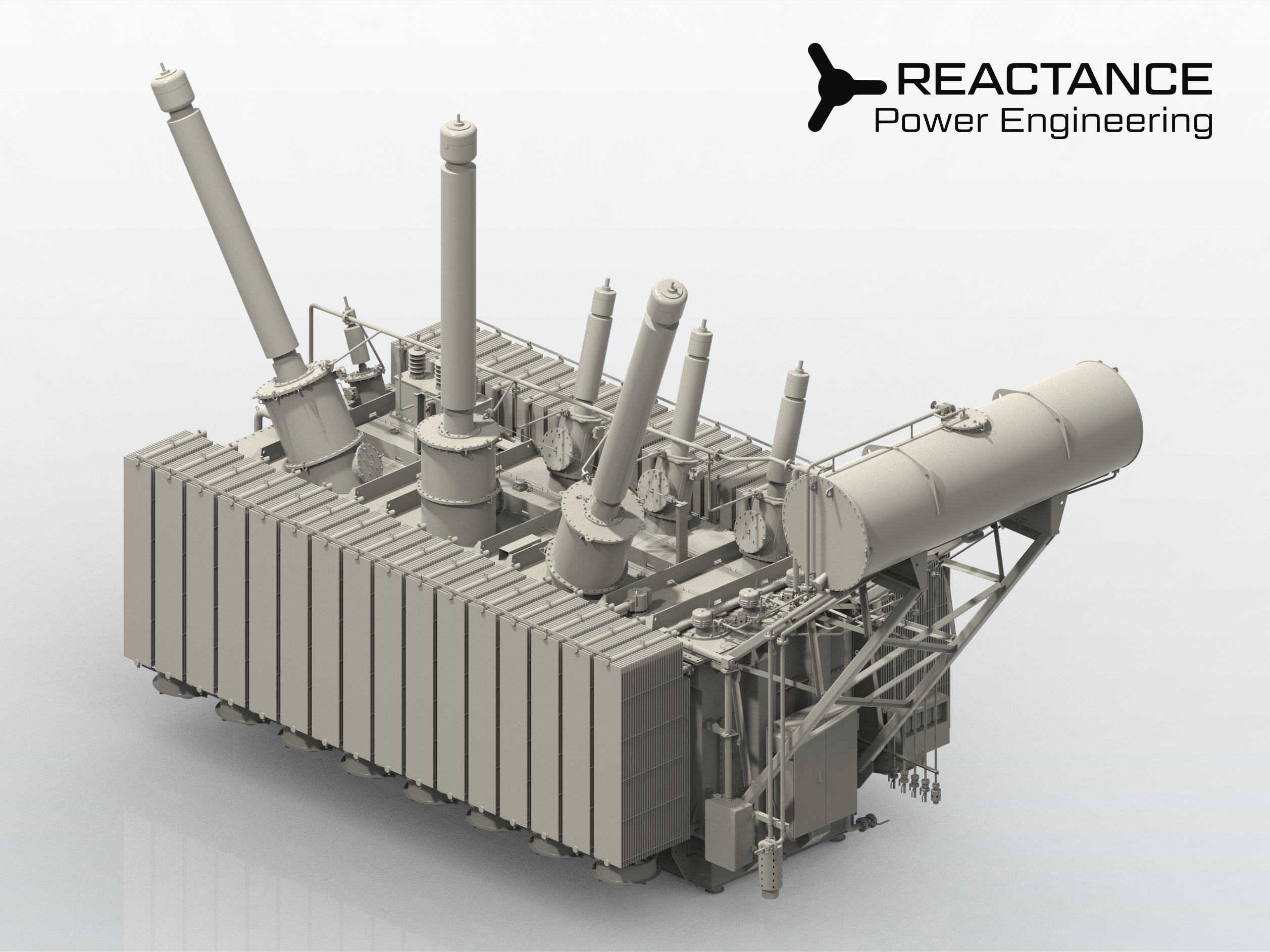
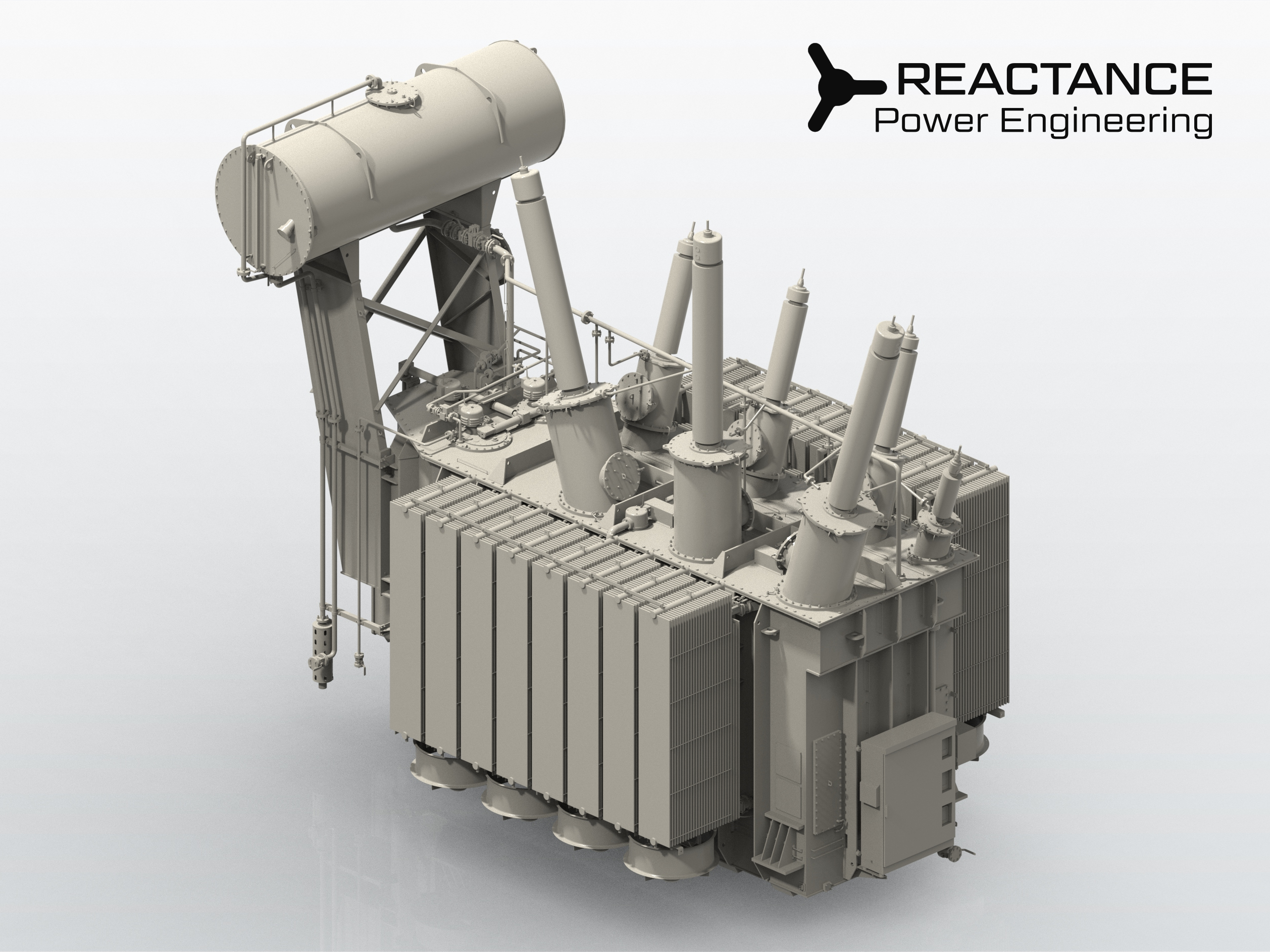
500 kV High-Power Autotransformer: Logistics Optimization
Challenge
Designing a massive 210 MVA, 500 kV unit within a strict 120-ton rail transport limit. The goal was to ensure compatibility with standard rail platforms, avoiding the extreme costs and delays associated with heavy-load specialized carriers.
What we did
To achieve a compact active part, we utilized a 4-column core system. This allowed us to strategically place the regulation and compensation windings on the side limb, optimizing the internal geometry and reducing the overall weight without sacrificing dielectric strength or performance.
Result
Logistics Optimization: By meeting the 120-ton limit, we enabled standard rail transit, cutting shipping costs by 40% and reducing transportation time by 1.5x.
Technical Compliance: Delivered a robust, high-current regulation solution tailored for extra-high voltage (EHV) grid stability.
| Type | One-phase autotransformer |
| Rated power, MVA | 210/210/60 |
| Rated voltage (HV/MV/LV), kV | 500/110/10 |
| Vector group | YNa0d11 (three-phase bank) |
| Voltage regulation, range, No. of steps | OLTC on MV side, ±6×2% |
| Rated frequency, Hz | 50 |
| Cooling system | ONAN/ONAF/OFAF |
| Special requirements | High TC Rated Through-Current |
240 MVA Autotransformer: Advanced Stray Flux Management
Challenge
The project required a 240 MVA Star-Star unit, strictly prohibiting a delta winding. At this power level, the lack of a tertiary winding generates intense stray fields, risking eddy-current induction and severe hotspots in the tank and structural steel.
What we did
We conducted a series of Advanced 3D Magnetic Field Simulations across multiple load regimes. By precisely mapping flux destribution, we identified potential hotspots. Based on these insights, we optimized the geometry of the flux collectors and internal metallic structure to effectively redirect stray flux, ensuring thermal stability.
Result
Thermal Integrity: Passed all temperature rise tests with zero hotspots detected, validating the precision of our stray flux mitigation strategy.
Grid Compatibility: Successfully delivered a robust, high-power solution that meets the client’s specific grid requirements.
| Type | Three-phase autotransformer |
| Rated power, MVA | 240 |
| Rated voltage (HV/LV), kV | 230/138 |
| Vector group | YNa0 |
| Voltage regulation, range, No. of steps | OLTC on HV side, ±10×1,5% |
| Rated frequency, Hz | 50 |
| Cooling system | ONAN/ONAF |
| Special requirements | No-Delta Winding (Star-Star) |
63 kV Power Transformers for Large-Scale Wind Farms
Challenge
The project demanded high-level fire safety protection. We were required to integrate the SERGI Fire Prevention solution without increasing the transformer's overall footprint. Additionally, the client mandated an IP66/67 protection rating for all secondary circuits.
What we did
We engineered an ultra-compact equipment layout, strategically positioning the Oil & Gas Separation Tank to maintain the original footprint. To meet the ingress protection requirements, all secondary wiring was housed in high-grade certified flexible conduit systems. We utilized 3D CAD cabling design to optimize routing and ensuring clean aesthetic.
Result
Safety Integration: Successfully integrated an active fire prevention system within a constrained space.
Operational Durability: Achieved IP66/67 rating across all control systems, ensuring long-term resilience for wind farm operations.
| Type | Three-phase two winding transformer |
| Rated power, MVA | 50 |
| Rated voltage (HV/LV), kV | 63/20 |
| Vector group | YNd11 |
| Voltage regulation, range, No. of steps | OLTC on HV side, ±8×1,578% |
| Rated frequency, Hz | 50 |
| Cooling system | ONAN/ONAF |
| Special requirements | SERGI Transformer Protection |
330 kV Autotransformer: Value Engineering & Compact Design
Challenge
A classic 200 MVA, 330 kV autotransformer project. The primary objective was to modernize the design while significantly reducing material intensity and manufacturing costs without compromising strict GOST standards or technical reliability.
What we did
We re-engineered the layout by implementing a "cluster" configuration of three single-phase OLTCs, allowing us to drastically shrink the internal tank dimensions. We also integrated a single motor-drive unit to synchronize all three phases, replacing the traditional two-drive setup.
Result
Cost & Material Optimization: By eliminating one MDU and reducing total weight by 20 tons, we significantly lowered raw material costs and enhanced project margins.
Logistical Advantage: The more compact footprint simplified site installation and reduced the oil volume required for commissioning.
| Type | Three-phase autotransformer |
| Rated power, MVA | 200/200/10 |
| Rated voltage (HV/MV/LV), kV | 330/115/38.5 |
| Vector group | YNa0d11 |
| Voltage regulation, range, No. of steps | OLTC on HV side, ±6×2% |
| Rated frequency, Hz | 50 |
| Cooling system | OFAF |
| Special requirements | GOST Standard |
250 MVA Autotransformer with Split LV Windings
Challenge
Designing a complex 250 MVA unit with split LV windings. Split designs are inherently susceptible to extreme axial forces during specific short-circuit scenarios. Additionally, the project required cable bushings 230 kV and 120 kV.
What we did
We performed high-fidelity modeling of all potential short-circuit modes to calculate peak dynamic forces. Based on these simulations, we engineered a reinforced windings clamping system to ensure structural integrity during emergency faults. To streamline the project, we designed modular cable boxes compatible with temporary air bushings for the FAT.
Result
Mechanical Resilience: Verified structural stability against extreme SC forces, ensuring high operational reliability.
Testing Efficiency: The adaptable cable box design eliminated testing bottlenecks, ensuring the unit met all dielectric requirements.
| Type | Three-phase autotransformer with split windings |
| Rated power, MVA | 250/250/62.5-62.5 |
| Rated voltage (HV/MV/LV), kV | 230/121/11 |
| Vector group | YNa0d11d11 |
| Voltage regulation, range, No. of steps | OLTC on HV side, ±13×0,573% |
| Rated frequency, Hz | 50 |
| Cooling system | OFAF |
| Special requirements | Cable bushings |
Let's build something great together.
Get in touch →| Type | TBD |
| Rated power, MVA | TBD |
| Rated voltage, kV | TBD |
| Vector group | TBD |
| Voltage regulation, range, No. of steps | TBD |
| Rated frequency, Hz | TBD |
| Cooling system | TBD |
| Special requirements | TBD |
Most Reactance assignments are performed under strict confidentiality. For this reason, client names, OEMs and project locations are not disclosed publicly. The following anonymized references illustrate the type, scale and complexity of our work. More detailed references may be shared under NDA.